

How to Oxy/Acetylene Weld
Buy Welding supplies online at metals4U
WARNING:
This document contains general information about the topic discussed herein. This document is not an application manual and does not contain a complete statement of all factors pertaining to that topic.
The installation, operation and maintenance of arc welding equipment and the employment of procedures described in this document should be conducted only by qualified persons in accordance with applicable codes, safe practices, and manufacturers' instructions.
Always be certain that work areas are clean and safe and that proper ventilation is used. Misuse of equipment, and failure to observe applicable codes and safe practices can result in serious personal injury and property damage.
Introduction
Oxygen/Acetylene welding, or "Gas Welding", is a process which relies on combustion of oxygen and acetylene. When mixed together in correct proportions within a hand-held torch or blowpipe, a hot flame is produced with a temperature of about 3,200° The chemical action of the oxy/acetylene flame can be adjusted, by changing the ratio of the volume of oxygen to acetylene, using the valves on the torch or blowpipe.

Equipment
Oxy/acetylene equipment is portable and easy to use. It comprises oxygen and acetylene gases stored under pressure in steel cylinders. The cylinders should be fitted with regulators, to control the pressure and flow of gases. Flexible hoses are used to connect the regulators to the torch or blowpipe. Specially designed safety devices, called flame traps or "Flashback Arrestors" are fitted between the hoses and the regulators. Flashback arrestors prevent flames generated by a 'flashback' from reaching the cylinders
Flashbacks
A flashback is a rapid, high- pressure flame travelling back up the gas hoses, caused by welding or cutting at incorrect pressure settings, or from blockage or overheating of the nozzle (for example by operating with the nozzle too close to the material)
Flashbacks can result in extremely dangerous cylinder ignition and must be prevented by proper use of working Flashback Arrestors.
Lighting-Up Procedure
To begin oxygen/acetylene welding or cutting, open theFig. 1 Oxy/Acetylene Equipment cylinder valves slowly by means of the cylinder key(s).
Do not open suddenly or there may be serious damage to the regulator and the possibility of an accident. Open the cylinder valve spindles one turn only. Open the fuel gas control valve on the blowpipe and adjust the regulator to give the correct working pressure, this ensures that any air or oxygen is purged from the hose. Repeat the procedure for the oxygen side.
Light the gas by means of a suitable sparklighter making sure that the sparklighter is held at right angles to the nozzle. Do not use liquid igniters (such as cigarette lighters) as the vapour/gas combination can be dangerous.
Reduce or increase the acetylene supply to the blowpipe valve until the flame just ceases to smoke.
Slowly increase the oxygen via the blowpipe control valve until the white inner cone in the flame is sharply defined with the merest trace of an acetylene haze. The blowpipe is now correctly adjusted.
WELDING TECHNIQUES
Leftward Welding
Leftward Welding is used on steel for flanged edge welds, for unbevelled plates up to 5.0mm (3/16in). It is also the method usually adopted for cast iron and non-ferrous metals. Welding is started at the right-hand end of the joint and proceeds towards the left.

Fig. 2 Leftward welding
The blowpipe is given a forward motion with a slight sideways movement to maintain melting of the edges of both plates at the desired rate and the welding rod is moved progressively along the weld seam – see fig. 2. The sideways motion of the blowpipe should be restricted to a minimum.
Rightward and all position rightward welding
Rightward welding is recommended for steel plate over 5.0mm (3/16in) thick. Plates from 5.0mm to 8.0mm (3/16in to 5/16in) need not be bevelled; over 8.0mm (5/16in) the edges are bevelled to 30o to give an included angle of 60o for the welding V. Suitable for horizontal/vertical position.

Fig. 3 Rightward Welding
The weld is started at the left-hand end and moves towards the right with the blowpipe flame preceding the filler rod in the direction of travel. The rod is given a circular forward motion and the blowpipe is moved steadily along the weld seam – See Fig. 3 This is faster than leftward welding and consumes less gas; the V angle is smaller, less filler rod is used and there is less distortion. The all-position rightward technique is a modification of the above and is particularly suitable for mild steel plate and pipe in the vertical and overhead position – See Fig. 4.

Fig. 4 All-position rightward welding. Butt-welds in mild 5 - 8mm (3/16 - 5/16in) thick.
The advantages are that it enables the welder to obtain a uniform penetration bead and an even build-up, particularly in fixed position welding; the welder can work with complete freedom of movement and has a clear view of the weld pool and the fusion zone of the joint. Considerable practice is required to become familiar with this technique even by operators skilled in normal downhand rightward welding. An apparent undercutting of the plate surface at the edges of the weld bead is a fault to which this technique is prone but this can be controlled by appropriate manipulation of the rod and flame. The rod and blowpipe angle should be adjusted to give adequate control of the molten metal as in normal rightward welding.

Fig. 5 Vertical welding, single-operator for plate thicknesses up to 5.0mm (3/16in)
Vertical Welding
Vertical welding may be used on unbevelled steel plate up to 3mm (1/8in) thickness and up to 15mm (5/8in) when two welders are employed working on both sides of the joint; welding starts at the bottom and proceeds vertically. See Fig. 5 and 6 for methods of blowpipe and welding rod manipulation for single-operator techniques.
When the two-operator method is used, the two welders must be trained to work in harmony.

Fig.6 Vertical welding, two operators for plates thicker than 5.0mm (3/16in)
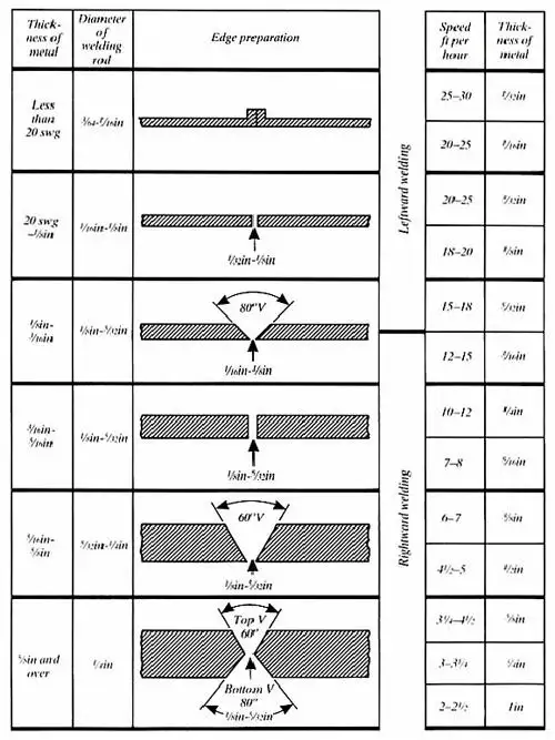
Fig. 7 Edge preparations
Bronze Welding
Bronze Welding involves the use of alloy bronze rods and is used for making joints in copper, for joining dissimilar metals, and for repairs to cast iron.
Among the rods used are fluxobronze, a flux-coated silicon bronze, plain silicon bronze, plain nickel bronze and manganese bronze with suitable flux.
It is essential that the edges of the materials should not be melted but merely raised to red heat. For example when bronzewelding cast iron, a manganese bronze rod should be used; this melts at 895º C, well below the melting point of cast iron. The fracture, or the edges of the metal to be joined are prepared in the usual manner, care being taken to ensure that all sharp edges are rounded-off and that they are absolutely clean. The joint so formed has excellent mechanical properties and providing there is no objection to dissimilarity in colour, bronzewelding can be recommended for a variety of purposes.
Fractured castings should be pre-heated before welding.
Depositing Hardfacing Rods
This is a process which consists of laying down a hard deposit which is very resistant to wear on a steel or cast iron surface and finds wide application in building-up wearing services on well-boring drills, dies, picks, valve seats, punches, knives, crushing and excavating machinery, etc.
For steel, the flame is adjusted to an excess of acetylene to give a feather of 1 ½ to 2 ½ times the length of the normal neutral inner cone. The steel is raised to a dull red-heat and when the surface begins to 'sweat' the rod is deposited on the surface – see Fig. 8. Upon completion the work must be cooled slowly either in a furnace or in lime or mica dust.
The deposition of hardfacing on cast iron is not as successful as on steel. Since cast iron cannot be made to 'sweat' it is advisable first to fuse a layer of hardfacing rod on to the surface as in the case of welding using a Cast Iron flux, then to 'sweat' a second layer onto the previous deposit.
Rods containing tungsten carbide are also deposited with this technique.

Fig. 8 Hardfacing Procedure
Building-up worn surfaces (Hardfacing)
For building-up surfaces subject to a large amount of wear it is usual to deposit a rod, which has special wear- resisting properties. An excess acetylene flame is used to deposit the metal; the base metal is pre-heated, as stated above and when it begins to 'sweat' the rod is melted on to the surface. The weld metal should be added in small deposits and the whole surface gradually built up to the required thickness. There is a wide range of high-carbon and alloy steel rods which, with appropriate flame adjustment, may be used for building up gear teeth, splines, keyways and worn parts in general.
Nozzle Maintenance
Do not maltreat a nozzle. Do not use it as a hammer or lever.
To clean nozzle orifices, sets of special nozzle cleaning reamers are available from your local distributor, see Fig.9. Should these not be available use a drill one size smaller than the orifice and work it up and down without twisting; the drill should be held in a pin vice. If the drill does not enter easily start with a smaller drill increasing the size until the correct diameter is attained. Effective flame shape can only be maintained if gas orifices are sharp and square with the end of the nozzle. If a nozzle becomes damaged on the end, rub it down with a sheet of fine emery laid on a flat surface such as a sheet of glass taking care to keep to keep the nozzle square with the rubbing service. The orifice should then be cleaned out as described above. The nozzle has been designed to make this reconditioning possible.
DO NOT use other than recommended wire reamers or broaches to clean out the orifices.

Fig.9 Nozzle Cleaning

Type 3 Shank & Cutter
L/W Shank & Cutter
NM Style Cutting Torch
Fig. 10 Styles Of Cutting Torch Equipment ("blowpipes")
N.B. It is essential when using a combined outfit (Type 3 or L/W) to open the oxygen valve or the shank fully. If this is not done there will be starvation of oxygen at the nozzle when the cutting oxygen lever is depressed.
CUTTING TECHNIQUES
General
Assemble the equipment and arrange the material to be cut in a convenient position; faster cutting and a smoother finish are possible if rust and scale are removed from the path of the cut. Light up the nozzle and hold the blowpipe with the nozzle at right angles to the plate and apply the heating flame to the edge of the material furthest from the operator. A spade or nozzle attached to the nozzle is of assistance in holding the blowpipe steady.
When the edge of the metal attains a bright red heat, operate the cutting oxygen lever and draw the blowpipe towards the body along the line of cut at a speed recommended in the data tables.
The above remarks apply to the severance of mild steel plate of normal thickness. The following points should be noted for differing cutting requirements.

Fig. 11 Cutting torch position basics
Thick Material
Because of heavy gas consumption when cutting thick material, ensure that there is an adequate supply of fuel gas and use a battery of oxygen cylinders coupled together or pipeline supplies. On very thick material, a cut may be started on the bottom face; gradually work up the edge with the blowpipe until the top is reached then continue the cut in the usual manner.
Painted and Galvanised Material
Clean the surface before starting to cut. It is often an advantage to incline the tip of the nozzle toward the body to help to undercut paint or scale. Unless ventilation is very good fume extraction should be installed at the point of cutting. In some cases it may be necessary to use a respirator as well.
Round Bar
Nick the bar with a chisel at the point where cutting is to start, alternatively apply the end of a piece of steel wire heated to a bright red.
Hole Cutting
For cutting holes in mild steel plate or pipe, mark out the area to be removed; cutting should be commenced within the area that will become scrap.
Within the scrap area, heat a spot to a bright red heat then very slowly operate the cutting oxygen control until a hole is pierced through the material. Now move the blowpipe at cutting speed to the edge of the area to be removed and follow round the marked out contour until the scrap portion is severed from the parent metal.
When using a pierce start it is important that the cutting oxygen valve is opened slowly to avoid a splash of hot metal and that the nozzle be presented at a slight angle so as to avoid slag being thrown back onto the nozzle.
Cast Iron
Apply the technique shown in Fig.12. The heating flame should be trimmed to give a large access of acetylene so that the cone has a length of 50 to 75mm (2 to 3in) before cutting oxygen is turned on. Only high pressure dissolved acetylene can be used for cutting cast iron.
It is not possible to cut a clean edge and because of the large amount of heat produced it is advisable to wear gauntlets and protective clothing.

Fig.12 Cutting Cast Iron
Cutting Nozzle Maintenance

Fig.13 Nozzle cleaning
Do not maltreat a nozzle. Do not use it as a hammer or a lever. To clean nozzle orifices, sets of special nozzle cleaning reamers are available from your welding distributor, see Fig.13. Should these not be available use a drill one size smaller than the orifice and work it up and down without twisting; the drill should be held in a pin vice. If the drill does not enter easily, start with a smaller drill, increasing the size until the correct diameter is attained. It is most important that the small holes at the seating end of the nozzle are not enlarged in any way, because this may alter the gas flow, and make cutting very difficult.
Effective pre-heat shape and cutting oxygen stream can only be maintained if gas orifices are sharp and square with the end of the nozzle. If a nozzle becomes damaged on the end, rub it down with a sheet of fine emery laid on a flat surface such as glass, taking care to keep the nozzle square with the cutting surface. The orifices should then be cleaned out as described above. The nozzle has been designed to make this reconditioning possible and as much as 3mm (1/18in) may be removed before a nozzle becomes unserviceable.
N.B. High speed venture type nozzles and two piece propane nozzles should not be treated in this way. Seek advice from your distributor.
Typical Variables For Welding & Cutting
Settings for Oxy/Acetylene Welding with Type 3 Welding equipment
Mild Steel thickness |
Nozzle size |
Operating pressure |
Gas consumption |
||||||||
Acetylene |
Oxygen |
Acetylene |
Oxygen |
||||||||
|
mm |
in |
swg |
bar |
psi |
bar |
psi |
l/h |
Ft3 |
l/h |
Ft3 |
|
|
0.9 |
|
20 |
1 |
0.14 |
2 |
0.14 |
2 |
28 |
1 |
28 |
1 |
|
1.2 |
|
18 |
2 |
0.14 |
2 |
0.14 |
2 |
57 |
1 |
57 |
1 |
|
2.0 |
|
14 |
3 |
0.14 |
2 |
0.14 |
2 |
86 |
3 |
86 |
3 |
|
2.6 |
|
12 |
5 |
0.14 |
2 |
0.14 |
2 |
140 |
5 |
140 |
5 |
|
3.2 |
1/8 |
10 |
7 |
0.14 |
2 |
0.14 |
2 |
200 |
7 |
200 |
7 |
|
4.0 |
3/32 |
8 |
10 |
0.21 |
3 |
0.21 |
3 |
280 |
10 |
280 |
10 |
|
5.0 |
3/16 |
6 |
13 |
0.28 |
4 |
0.28 |
4 |
370 |
13 |
370 |
13 |
|
6.5 |
1/4 |
3 |
18 |
0.28 |
4 |
0.28 |
4 |
520 |
18 |
520 |
18 |
|
8.2 |
5/16 |
0 |
25 |
0.42 |
6 |
0.42 |
6 |
710 |
25 |
710 |
25 |
|
10 |
3/8 |
4/0 |
35 |
0.63 |
9 |
0.63 |
9 |
1000 |
35 |
1000 |
35 |
|
13 |
1/2 |
7/0 |
45 |
0.35 |
5 |
0.35 |
5 |
1300 |
45 |
1300 |
45 |
|
25 |
1+ |
|
90 |
0.63 |
9 |
0.63 |
9 |
2500 |
90 |
2500 |
90 |
Settings for Oxy/Acetylene Cutting with Type 3 or NM Cutting Torches
Mild Steel thickness |
Nozzle size |
Operating pressure |
Gas consumption |
Cutting speeds |
||||||||||
Oxygen |
Acetylene |
Cutting Oxygen |
Heating Oxygen |
Acetylene |
||||||||||
|
mm |
In |
bar |
psi |
bar |
psi |
l/h |
Ft3/h |
l/h |
Ft3/h |
l/h |
Ft3/h |
mm.m |
In.m |
|
|
Sheet |
Asnm |
1.5 |
20 |
0.14 |
2 |
800 |
28 |
85 |
3 |
85 |
3 |
- |
- |
|
|
6 |
¼ |
1/32 |
1.8 |
25 |
0.14 |
2 |
800 |
28 |
480 |
15 |
400 |
14 |
510 |
20 |
|
13 |
½ |
3/64 |
2.1 |
30 |
0.21 |
3 |
1900 |
67 |
570 |
20 |
510 |
18 |
480 |
19 |
|
25 |
1 |
1/16 |
2.8 |
40 |
0.14 |
2 |
4000 |
140 |
540 |
19 |
470 |
17 |
400 |
16 |
|
50 |
2 |
1/16 |
3.2/3.5 |
45/50 |
0.14 |
2 |
4500 |
160 |
620 |
22 |
560 |
19 |
300 |
12 |
|
75 |
3 |
1/16 |
3.5/4.2 |
50/60 |
0.14 |
2 |
4800 |
170 |
680 |
24 |
620 |
22 |
205 |
8 |
|
100 |
4 |
5/64 |
3.2/4.8 |
45/70 |
0.14 |
2 |
6800 |
240 |
850 |
30 |
790 |
27 |
150 |
6 |
|
150 |
6 |
3/32 |
3.2/5.5 |
45/80 |
0.21 |
3 |
9400 |
330 |
960 |
34 |
850 |
30 |
125 |
5 |
|
200 |
8 |
1/8 |
4.2 |
60 |
0.28 |
4 |
14800 |
510 |
1380 |
48 |
1250 |
44 |
100 |
4 |
|
250 |
10 |
1/8 |
5.3 |
75 |
0.28 |
4 |
21500 |
760 |
1560 |
55 |
1420 |
50 |
75 |
3 |
|
300 |
12 |
1/8 |
6.3 |
90 |
0.28 |
4 |
25000 |
880 |
1560 |
55 |
1420 |
50 |
50 |
2 |
Settings for Oxy/Acetylene Gouging with Type 3 or NM Cutting Torches
Material thickness |
Nozzle size |
Operating pressure |
Gas consumption |
Cutting speeds |
||||||||||
Oxygen |
Acetylene |
Cutting Oxygen |
Heating Oxygen |
Acetylene |
||||||||||
|
mm |
In |
bar |
psi |
bar |
psi |
l/h |
Ft3/h |
l/h |
Ft3/h |
l/h |
Ft3/h |
mm.m |
In.m |
|
|
8 |
5/16 |
13 |
4.0 |
60 |
0.5 |
7 |
3680 |
130 |
990 |
35 |
905 |
32 |
610 |
24 |
|
11 |
7/16 |
19 |
5.0 |
75 |
0.5 |
7 |
9340 |
330 |
1870 |
66 |
1700 |
60 |
1070 |
42 |
|
12 |
1/2 |
25 |
5.5 |
85 |
0.55 |
8 |
16270 |
575 |
2290 |
81 |
2100 |
74 |
1220 |
48 |